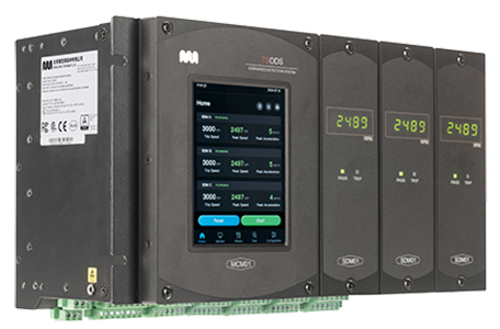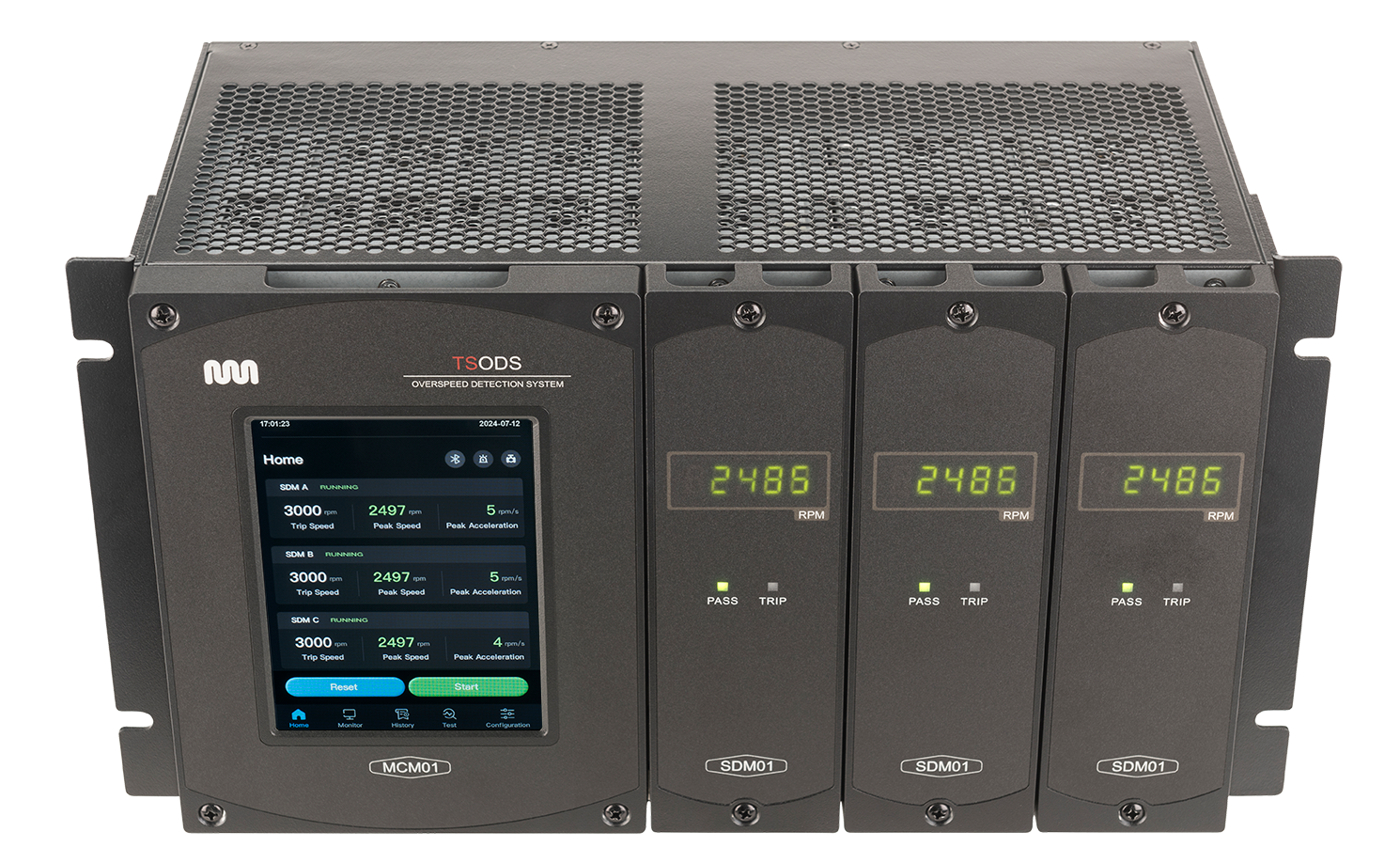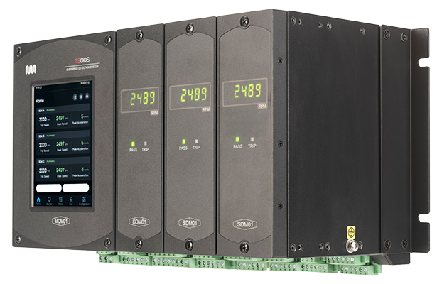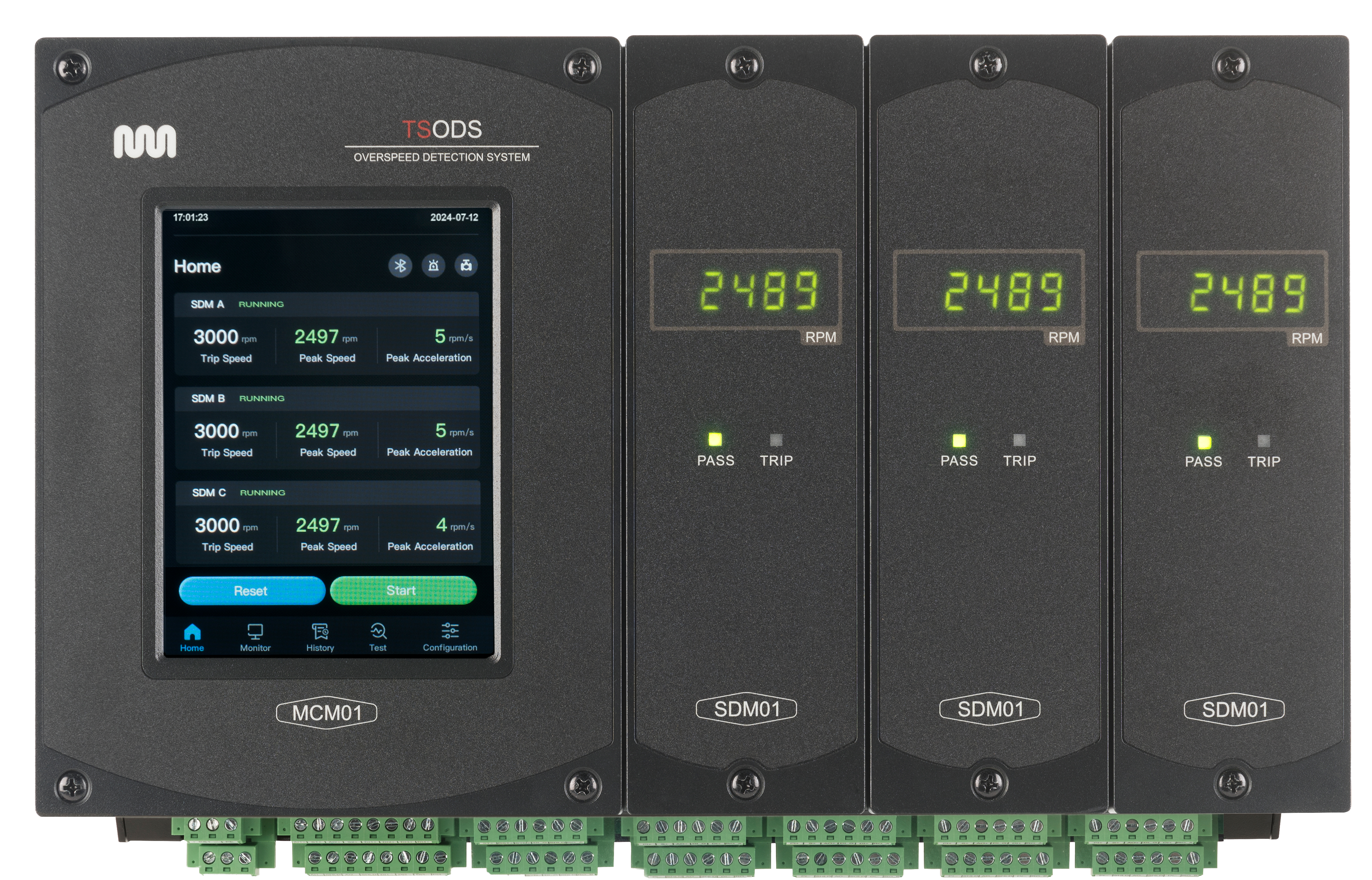
The TSODS is a TUV SIL-3-rated (with a 20-year proof test interval), API612 and API670 compliant, overspeed detection and protection system with ATEX and CSA/UL hazardous location certification. The TSODS is designed to replace a traditional mechanical trip-bolt or an obsolete electronic overspeed trip system on your steam or gas turbines, power turbines, (or other rotating equipment where ultra-reliable, precision overspeed detection and protection is essential).

Application Overview
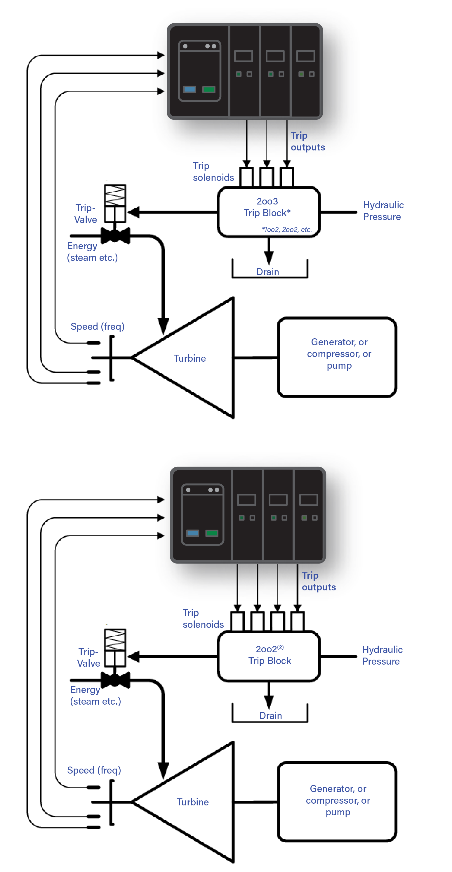
The TSODS is an advanced, triple redundant, TUV SIL3 rated, API 612, and 670 compliant overspeed detection system purpose-built to monitor and protect rotating turbomachinery equipment.
It’s an ideal overspeed detection system for both critical and non-critical steam, gas, and hydro-turbines used in various applications within the power, energy, and chemical industries.
Designed to detect overspeed events using rotational speed and acceleration measured with
active or passive magnetic pickups (MPUs) or eddy current probes, when an overspeed event is detected,
the TSODS communicates a shutdown directive to the turbine’s trip valve(s) or the relevant trip system.
FEATURES
- TUV IEC61508 SIL 3 certified, 2oo3 (two-out-of-three voting) logic meets and exceeds the functional requirements of API 670 (Section 8.4), and API 612
- CSA/UL, ATEX hazardous location certification
- 20 Year Proof Test interval
- Total response time ≤ 12msec: input to output (screw-to-screw)
- A wide speed range of 100 to 25,000 RPM allows the TSODS to protect virtually any turbomachinery train
- Configurable Acceleration Compensated Trip Setpoint (ACTS)
- Integrated TetraSentry Hydraulic Trip Interface testing
- Individual testing of force-guided safety relay 2oo3 voted outputs (four)
- Internal Frequency Generator to facilitate Automatic and Manual online testing (for each Speed Detection Module (SDM))
- "Side Stacked," Card-in-Cage, Plug and Play, architecture to facilitate online repair.
- "Local" Touch screen MCM option
- Redundant power supplies: accepts one or two external 24 VDC power sources
- Accuracy to 0.02% - the highest measurement accuracy available for overspeed detection
- Overspeed trip and test event logs (stored on removable event memory - SD micro card)
- Peak-hold on the highest detected speed stored for event analysis
- Four independent force-guided "safety" relay outputs (for each SDM), voted 2oo3 on the ODS backplane
- Form-C alarm relay outputs for each speed unit
- OPC UA, TCP Modbus, and Serial Modbus Communications
- Local, Serial, and Bluetooth Configuration
The TSODS is panel and EIA rack mountable using a side-stacked card-in-cage architecture for installation in an instrument/monitoring machine protection system cabinet. Optionally, it can be housed in a NEMA 4/4X enclosure, allowing it to be mounted outdoors on the turbine deck. The unit is self-contained with integrated termination hardware.
The Main communications Module (MCM) and the speed detection modules (SDMs) are online, plug-and-play replaceable.
The operator interface includes an optional touchscreen display, a PC-based configuration interface, a mobile application-based Bluetooth monitoring interface, serial and ethernet Modbus interfaces, and OPC UA connectivity.
 TSODS OVERSPEED DETECTION SYSTEM ARCHITECTURE
TSODS Architecture Overview
The TSODS system includes three speed detection modules (SDMs), a management and communication module (MCM), and a module terminal interface (MTI) that provides the cage and backplane to accommodate and connect the MCM and SDM modules.
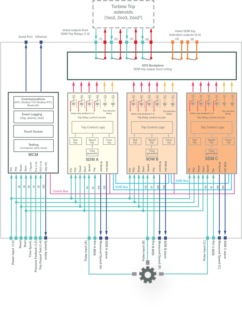
The MCM communicates with the three SDMs through the COM_BUS on the MTI backplane. The three redundant SDMs communicate with each other through the point-to-point SDM_BUS, which is also located on the MTI backplane. The TSODS interacts with external interfaces through Ethernet (Modbus TCP or OPC UA), an RS485 serial port, or Bluetooth BLE. Power for the TSODS is supplied by redundant 24vdc power supply terminations. The two power supply inputs are connected to the triple SDMs and MCM module through the MTI backplane.
The TSODS system provides two dedicated digital input interfaces for reset and start functions, and the reset and start signals enter the triple SDMs and MCM module, respectively, through the backplane. Each SDM module I/O includes (1) speed signal input, (1) forced trip signal input, (1) measured speed readout (4~20mA), and (1) alarm relay output. Each SDM provides 6 trip relay outputs, which are 2oo3 voted on the MTI backplane. The MCM I/O includes (1) dedicated clock synchronization signal input, (2) hydraulic trip block inter-valve cavity pressure feedback inputs (4-20mA), (4) test inputs, and (1) system alarm relay output, which are connected to the MCM via the MTI terminations and backplane.
SPEED DETECTION MODULE RELAY VOTING ARCHITECTURE
The TSODS achieves its extended proof test interval (20 years) in part by using relays with forcibly guided contacts (safety relays). Each of the three SDMs features force-guided relays for four out of the six trip outputs (two of the six trip outputs are intended to communicate trip status). All of the SDM relays are voted in a two-out-of-three schema on the TSODS MTI backplane.

| Module | Type | Number | Description |
| SDM/MTI | Digital Output | 4 |
2oo3 voted, Force-Guided Safety Relay Outputs |
| SDM/MTI | Digital Output | 2 | 2oo3 voted, general purpose trip relay (for indication |
| SDM (total) | Digital Output | 1(3) | SDM module alarm |
| SDM (total) | Frequency Input | 1(3) | Active, Passive, or Eddy Current speed input |
| SDM (total) | Digital Input | 1(3) | External trip input |
| SDM (total) | Analog Output | 1(3) | Measured speed indication |
| MCM | Digital Input | 1 | Reset |
| MCM | Digital Input | 1 | Start |
| MCM | Digital Input | 1 | Time Synch |
| MCM | Analog Input | 2 | Tetrasentry interavity pressure (solenoid test feedback) |
| MCM | Digital Input | 4 | Manual Force Guided Relay test/trips |
| MCM | Digital Output | 1 | System Alarm |
| MCM | DB9 Serial Comms | 1 | Modbus RTU communications |
| MCM | RJ45 | 1 | Modbus TCP communications |
TSODS OVERSPEED DETECTION SYSTEM MODULES
MAIN COMMUNICATIONS MODULE (MCM)
The MCM has two variations, one with and one without a touchscreen human machine interface. Both variations provide external communications (serial and Ethernet), as well as a Bluetooth BLE interface. The MCM communicates with each SDM via the Comm_Bus on the MTI backplane.
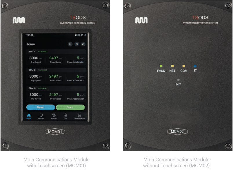
| Feature | MCM with Touchscreen | MCM without Touchscreen |
| Dual-core CPU, 800 Mhz main frequency | included | included |
| Ethernet Interface (OPC UA/Modbus TCP) | included | included |
| RS485 Serial Interface (Modbus RTU) | included | included |
| Bluetooth BLE 5.0 interface | included | included |
| Removable Micro SD memory card (event log storage) | included | included |
| Reset and Start hardwired digital input | included | included |
| Clock Synchronization input (time synchronization) | included | included |
| Trip test input (manually trip outputs) | included | included |
| System Alarm (relay output) | included | included |
| 5.6-inch resistive touch screen HMI | included | not included |
| Manual Overspeed Testing | included | not included |
| Automatic Overspeed Testing | included | not included |
| Automatic Tetrasentry Trip Output Testing | included | not included |
| Two 4-20mA analog inputs (Tetrasentry Pressure) | included | not included |
SPEED DETECTION MODULES (SDM)
The TSODS includes three independent speed detection modules. Each module compares its measured speed input with the configured overspeed trip threshold and drives its respective trip outputs accordingly. The three independent SDMs form the TMR architecture to achieve unparalleled safety and availability.

Three Speed Detection Modules - typical for each TSODS
| Feature (for each SDM) |
| Dual-core CPU, 800 Mhz main frequency |
| (1) Passive, Active, or Proximity probe Speed Input, 0.5Hz to 32KHz |
| (1) Manual trip input |
| (4) TUV Certified SIL 3 trip relays, 3A, NO contacts |
| (2) General purpose trip indication relays, 2A, NO contacts |
| (1) Alarm output relay, 2A, NO contacts |
| (1) Speed Readout analog output, 4-20mA, ±0.1%, @ 25° C) |
MODULE TERMINATION INTERFACE (MTI)
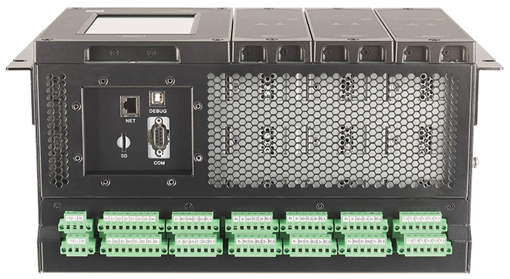
The MTI provides the cage and backplane to accommodate and connect the MCM and SDM modules. It also provides the electrical power connection, interconnected communications buses for the MCM and SDM, and the instrument wiring termination interface.

MTI Cage, Backplane, Field Termination Interface

TSODS MTI Connection Diagram
TSODS User Interface
There are three distinct and separate ways for Users to interface with the TSODS: the MCM touchscreen*, the Windows PC or notebook-based configuration software, or the iOS and Android Mobile Applications running on a smartphone or tablet.
MCM Touchscreen Interface
The MCM01 Touchscreen is a self-contained human-computer interface (processor with a 5.6-inch touchscreen) that provides local access to functions such as enhanced status monitoring, parameter configuration, log recording, and online testing.

- Status Monitor: Real-time monitoring of the TSODS status and diagnostics, graphical and contextual I/O operational data, and alarm information.
- Configuration: Provides current configuration parameters in both graphically and contextually as well as the ability to modify configuration parameters online (with appropriate credentials).
- Test: Access to conduct the overspeed testing both manual and automatic, automatic valve sequence test (for TetraSentry) and ODS indicator light test.
- Event Review: Access to read event logs, save event logs to micro SSD , log save, clear logs (with proper access authority, clear peak speed (with proper access authority)
PC Windows™ based Configuration Interface
The TSODS Configurator software is a "drop-down", menu-driven configuration and monitoring interface that runs on a Windows PC or notebook computer and connects with the TSODS through a proprietary communication protocol using an Ethernet communications interface.

- Status Monitor: Real-time monitoring of the TSODS status and diagnostics, graphical and contextual I/O operational data, and alarm information.
- Configuration: Provides current configuration parameters in both graphically and contextually as well as the ability to modify configuration parameters both off and online (with appropriate credentials).
- Test: Access to conduct both manual and automatic overspeed testing as well as the automatic valve sequence test (for TetraSentry), and ODS indicator light test.
- Event Review: Access to read event logs, save event logs to micro SSD, save logs, clear logs (with proper access authority, clear peak speed (with proper access authority)
Mobile Application (iOS and Android)
The TSODS supports one low-power (less than six meters) Bluetooth (BLE) port and Bluetooth5.0 communication protocol. It can communicate with the mobile application software installed on iOS and Android smartphones or tablets. Through the Bluetooth interface, users can view the safety overspeed detector's configuration information, log information, and real-time status.

- Status Monitor (read-only*): Real-time monitoring of the TSODS status and diagnostics, graphical and contextual I/O operational data, and alarm information.
- Configuration view (read-only*): Provides current configuration parameters both graphically and contextually .
- Event Review (read-only*): Access to read event logs.
* configurable from the MCM01 interface or the PC Configuration tool.
|
Feature |
MCM Touchscreen |
PC Configurator |
Mobile Application |
|
Status Monitor: Real-time monitoring of the TSODS status and diagnostics, graphical and contextual I/O operational data, and alarm information. |
Included |
Included |
Included |
| Configuration: Provides the ability to modify configuration parameters on or offline (with appropriate credentials). |
Included |
Included |
Limited (if Enabled) |
| Configuration review: Provides access to current configuration parameters both graphically and contextually (read-only for Mobile Applications) |
Included |
Included |
Included |
|
Test: Access to conduct the overspeed testing both manual and automatic, automatic valve sequence test (for TetraSentry) and ODS indicator light test. |
Included |
not Included |
not Included |
| Event Access: Access/Save event logs on micro SSD , log save, clear logs (with proper access authority, clear peak speed (with proper access authority) |
Included |
Limited |
not Included |
| Event Review: Access to read event logs, (read-only for Mobile Applications) |
Included |
Included |
Included |
Overspeed Detection Software Features
-
-
-
-
-
-
-
-
-
Acceleration comprensated trip setpoint adjustment (ACTS)
-
Multiple testing and validation schema
-
Automated Tri-Sen TetraSentry hydraulic trip system testing
-
-
-
-
-
-
-
-
Acceleration Compensated Trip Setpoint (ACTS)
When the ACTS function is disabled, TSODS executes the overspeed trip function. Each SDM module detects the speed of the monitored equipment in real-time and compares it with the configured "normal overspeed trip setpoint" (nTSP) to detect the overspeed event and generate a trip command.
When the ACTS function is enabled, the TSODS executes the overspeed trip function based on a configurable acceleration-compensated overspeed trip setpoint (aTSP), effectively lowering the overspeed trip setpoint. The compensation is accomplished by comparing a configured acceleration value (Max_accel) to the actual measured acceleration, and adjusting the "calculated" overspeed trip setpoint between the normal trip setpoint and the acceleration compensated trip setpoint.
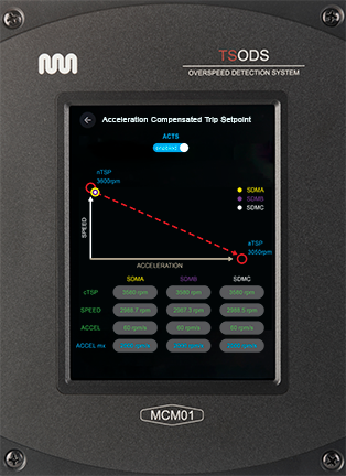
If the current measured acceleration is equal to zero, the calculated trip setpoint is equal to the normal trip setpoint. If the measured acceleration is equal to or greater than the maximum acceleration, the calculated trip setpoint is equal to the acceleration compensated trip setpoint.
The function for this compensation is:
cTSP = nTSP − [nT𝑆𝑃−aT𝑆𝑃 / 𝑀𝑎𝑥_𝑎𝑐𝑐𝑒𝑙]∗𝐴𝑐𝑐𝑒𝑙
cTSP = calculated actual overspeed trip setpoint
nTSP = configurable normal overspeed trip setpoint (highest overspeed trip setpoint)
aTSP = configurable acceleration compensated trip setpoint (lowest overspeed trip setpoint)
Max_accel = configurable maximum acceleration
Accel = actual measured acceleration
Manual and Automatic Overspeed Trip Testing
While the proof test interval for the TSODS is 20 years, the TSODS includes multiple overspeed testing schema. Depending upon the MCM configuration, the TSODS can have up to four different ways to accomplish overspeed testing.
 Local Temporary Overspeed Setpoint Test: The turbine overspeed test is initiated from the MCM (with touchscreen. It typically involves temporarily lowering the ODS overpeed trip setpoint below the normal trip setpoint and testing the turbine trip using the actual turbine speed.
 - Local manual simulated overspeed testing: This test uses the speed signal generated by the frequency generator within a given SDM to test a given SDM's overspeed trip function. Through the MCM (with touchscreen), the operator can manually increase/decrease the frequency from the SDM's internal frequency generator to validate an SDM's overspeed trip function.
- Local automatic overspeed testing: This test also uses the speed signal generated by the frequency generator within a given SDM to test a given SDM's overspeed trip function. Through the MCM (with touchscreen), the operator can initiate an automatic test using the frequency from the SDM's internal frequency generator to validate each of the SDM's overspeed trip functions.
- Remote automatic overspeed testing: The remote automatic overspeed testing is similar to the local automatic overspeed test with the added functionality of using a dedicated "write command" from a remote interface (using Modbus RTU, Modbus TCP, or OPC UA)
Tri-Sen TetraSentry Hydraulic Trip Interface and Testing

When the TSODS is coupled with the TetraSentry hydraulic trip interface, the TSODS "Auto Sequence Valve Test" function can be enabled to automatically test the TetraSentry online. While the TetraSentry has TUV-certified SIL 4+ reliability, it's strongly recommended that the TetraSentry cartridge valves are "exercised" on a regular basis to ensure they don't become "sticky" due to contaminated system oil. The TSODS is able to provide perfectly integrated, complete automation of this recommended testing/exercising along with recording and logging performance metrics.
This sequence valve test is intiated from the TSODS touch screen, by a dedicated write command on a communication port (Modbus RTU, Modbus TCP, OPC UA), or automatically by a configurable timer within the TSODS.
| Feature | Description |
|---|---|
| System trip response (DTT) | < 11.5 msec (screw to screw) - de-energize to trip |
| System trip response (ETT) | < 15.0 msec (screw to screw) - energize to trip |
| Feature | Description |
|---|---|
| Power | Two (2) redundant 24Vdc (19Vdc~32Vdc ) with anti-reverse polarity protected, SELV/PELV compliant, inputs |
| Power consumption | ≤ 50W |
| Feature | Description |
|---|---|
| Pulse/Frequency type |
Three (3) inputs (1/SDM): Passive Magnetic, Active Proximity, or Eddy Current
|
| Input Accuracy |
±0.2Hz @ < 100Hz, ±1Hz @ < 10KHz, ±0.01%FSR @ > 10KHz |
| Input | Description |
|---|---|
| SDM Trip | Three (3) inputs (1/SDM) 24vdc/32Vdc max (dry-NC or wet) |
| Start | One (1) common input, 24vdc/32Vdc max, (dry-NC or wet) |
| Reset | One (1) common input, 24vdc/32Vdc max, (dry-NC or wet) |
| Time Synchronization | One (1) input, 24vdc, (dry-NC or wet) |
| Manual Trip | Four (4) inputs (1/safety relay), 24vdc/32Vdc max, dry-NC or wet |
| Output | Description |
|---|---|
| Trip Outputs (trip outputs 1-4) | Four (4) Relay outputs, Normally Open (NO), Single Pole Single Throw (SPST), 3A@24Vdc |
| Trip Indicator (trip outputs 5-6) | Two (2) Relay outputs, Normally Open (NO), Single Pole Single Throw (SPST), 2A@24Vdc |
| SDM Alarm | Three (3) 1/SDM (1) Relay outputs, Normally Open (NO), Single Pole Single Throw (SPST), 2A@24Vdc |
| System Alarm | One (1) System Relay output, Normally Open (NO), Single Pole Single Throw (SPST), 2A@24Vdc |
| Input | Description |
|---|---|
| Hydraulic Trip Interface (TetraSentry) test | Two (2) 4-20mA, 2, 3, or 4 wire |
| Output | Description |
|---|---|
| Speed Readout | Three (3) 4-20mA signal measured range, output signal range 0-22mA, |
| Output Accuracy | ±0.1% @ 25 °C, ±0.5% (-20 / 60℃) |
| Feature | Description |
|---|---|
| Ethernet | One (1), RJ45, 100/1000Mbps, supports proprietary configuration protocol as well as OPC-UA, and Modbus TCP protocols |
| RS485 Serial | One (1) DB9 (Female), 9600/19200/18400/57600 and 115200bps, full or half-duplex, Modbus RTU (Slave) protocol. |
| Bluetooth | One (1) Bluetooth 5.0, ≥ 256Kbps, ≤ 6m transmission distance, communications slave |
| Feature | Description |
|---|---|
| TUV functional safety | TUV SIL 3, 20 year proof test interval |
| ATEX (hazardous location) | Zone 2,: II 3 G Ex ec nC IIC T4 Gc (-20°C ≤ Ta ≤ +60°C) |
| CSA (hazardous location) | Class 1, Div 2, Groups A,B,C,D, T4 (-20°C ≤ Ta ≤ +60°C) for use in US and Canada |
| CE | EMC: 2014/30/EU, LVD: 2014/35/EU, RoHS: 2011/65/EU |
| Bluetooth | FCC, BQB, RED |
| Anti-Corrosion | G3, ANSI/ISA S71.04 |
| Feature | Description |
|---|---|
| Operating Temperature | -20 ℃ to 60 ℃ |
| Storage Temperature | -20 ℃ to 70 ℃ |
| Relative Humidity | 10 % to 95% non-condensing |
| Altitude | ≤ 3000 meters |
| Vibration | 5 Hz ≤ f ≤ 8.4 Hz 3.5 mm peak constant displacement, sinusoidal 5 Hz ≤ f ≤ 150 Hz 10 m/s2 peak constant acceleration, sinusoidal |
| Shock | 150 m/s2 peak, 11ms duration, half-sine |
| Feature | Description |
|---|---|
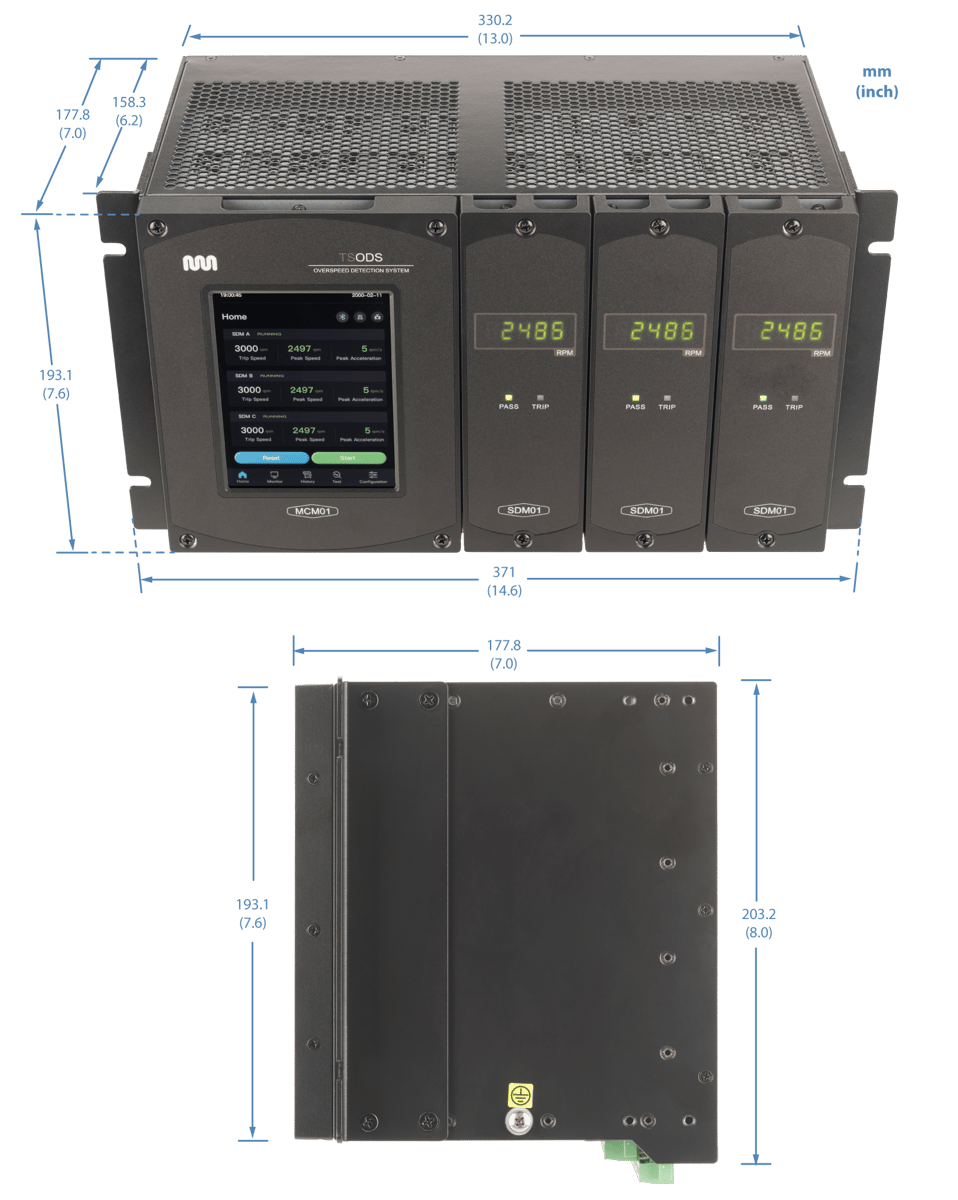
| Dimensions | 330.2 mm (13") x 203.2mm (8") x 177.8mm (7") |
| Weight | approximately* 13kg (28.7 lbs) - [MCM/3 SDMs/MTI Chassis] (*dependent upon mounting configuration, e.g. flat panel, EIA, etc.) |
DIMENSIONS
